
If you’ve ever experienced a roof leak you never forget it. What a mess! I remember looking up and seeing the spreading stain in our roof when I was stationed in Florida. Envisioning a the soggy mess that our house was about to become, I call a roof specialist and in panic mode explained what was happening. We were lucky to contact a company that was professional and took our panic in stride. We learned a lot and the completely soggy adventure we envisioned was avoided.
Here is some information about roofs that might be helpful in buying a house, talking to your insurance company about homeowners insurance, or helping to avoid panic mode should you be looking at a soggy mess on your ceiling.
Roof Shape Basics
A roof is one of the critical defining elements of any residential dwelling or building. The shape of a roof is important because it determines how well the structure can withstand certain environmental elements like wind and rain runoff. As a homeowner it is important to understand some basics about your roof shape and structure.
Typical Roof Shapes
Most roofs can be categorized into three basic shapes: Gable, Hip, and Flat (or Low Slope).
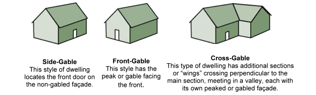
Gable
A gable roof is identified by a straight slope falling from the top ridge to the eave where the roof structure meets the upper wall sections. Visually, this creates a triangle shape above the walls on the side, front, or rear of a dwelling.
Below are some basic illustrations of some gable roofs:
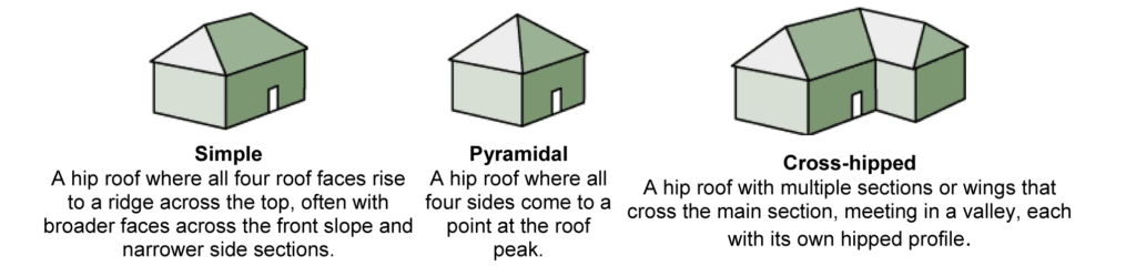
 Hip
Hip
A hip roof is easily identified by its “pyramid” shape. On a hip roof, the roof plane breaks along the slope line allowing the roof shape to “bend” or wrap around the structure creating “valleys” at each junction.
Below are some simple illustrations of some hip roofs:
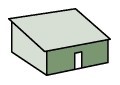 Flat
Flat
A flat or “low-slope” roof is self-explanatory. Many roofs in New Mexico fall in this category. Most building codes require that a flat roof must have a certain amount of slope to allow for rain runoff and to avoid standing water or “ponding”. To the left is a sample of a flat roof.
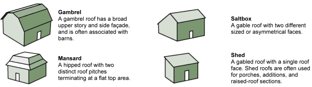
Additional Roof Shapes
Below are some simple illustrations of other roof shapes that are seen across the United States. All of these shapes can be seen in New Mexico:
Eave Details
The eave of a roof system is the outer edge of a roof that encompasses the entire perimeter of the roof. Most eaves are the “closed” type with a soffit section between the outer edge of the roof perimeter and the building wall.
Below is a breakdown illustration of a typical eave section:
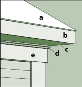 A. Roof – The upper exterior surface of the home.
B. Fascia – A flat horizontal band around a roof’s perimeter.
C. Soffit (Or Box Eave) –An overhang enclosed with a ventilated soffit section that runs horizontally from the eave edge to the side of the building.
D. Cornice –The decorative section just below the roofline. The cornice may be simple or ornate depending on building style.
E. Rake –The pitched edge of a gable roof. Rakes may be close, or extend from the building to allow for an overhang.
The complexity or simplicity of a roof design is normally a combination of engineering specifications and aesthetic preferences, but most roofs fall within the categories described above. Resistance to wind forces during extreme weather conditions is also a function of a roof’s design and shape. This is particularly important to insurance professionals to determination to determine your homeowner’s insurance policy. As A SkyTech client feel free to ask us questions ab0ut your roof and any details that we have provided in your inspection report.

 Saving On Energy Costs This Winter
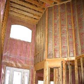
 When considering R-value as a means to determine the thermal resistance of a building component, there are other factors that must also be taken into account. While R-values are an excellent guide for comparing the attributes of different insulation products, they apply only when the insulation is properly installed.
 Calculating and Converting R-Value
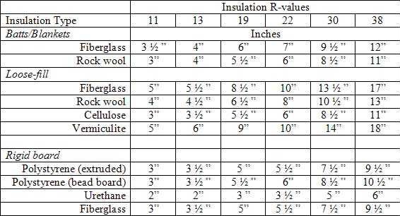
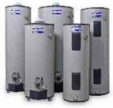
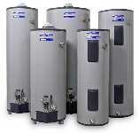
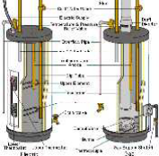 Tank Water Heater Construction
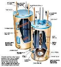 Heater Effectiveness
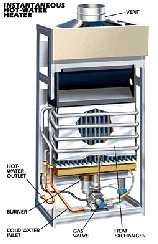 Tankless Unit Principle of Operation
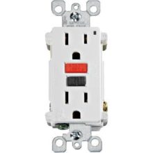
 Ground-Fault Circuit Interrupters (GFCIs)
 A PRACTICAL EXAMPLE OF A GROUND FAULT IN THE HOME
 BASIC OPERATION OF THE GFCI
 GFCI’S AND THE NATIONAL ELECTRICAL CODE (NEC)
 • All UL approved testers come with brief instructions. Read the instructions first!