Browse the SkyTech Library

Owning a home is the single most important investment most of us will make, and understanding how your home is constructed, as well as how the systems in the home operate is important.  YOUR SkyTech Team is constantly striving to make sure that you are equipped with the knowledge and understanding that will allow you to keep your home in good condition for years to come.

Here are some informational and technical articles and documents that we hope you and your clients will find interesting and helpful. Fee free to browse our technical library for any information that you may find interesting, informative, and helpful.  It’s just one more way that YOUR SkyTech Team is looking out for YOU!

Why have a New-Construction Phase-by-Phase Home Inspection?

Why have a New-Construction Phase-by-Phase Home Inspection?

Why request a New-Construction Phase-by-Phase Home Inspection from SkyTech New Mexico?

There are plenty of good reasons to have SkyTech of New Mexico perform a comprehensive, Third-Party New Construction Phase-by-Phase Inspection on your newly built home.

Buying a new house is likely one of, if not THE largest purchase decision you’ll ever make. At times, the entire process can seem to be fraught with emotion and stress.

A Professional, Third-Party New Construction Phase-by-Phase Inspection performed by a SkyTech of New Mexico Professional can help to substantially reduce any risks that may be associated with your large investment. It just makes good sense to learn as much as possible about the installation and serviceability of the systems and components in you newly built home from a neutral, experienced Professional.

Building a new home is a tremendously complex endeavor. It usually involves many people, sometimes separated as large groups of sub-contractors, technicians, and artisans. Even for the best of builders, oversights sometimes do occur. We here at SkyTech of New Mexico understand that.
Perhaps it’s a plumbing fixture that wasn’t leak-tested, or an electrical outlet / supply circuit that is incorrectly wired or not powered, or any one of dozens of minor problems that can easily be overlooked during such a major undertaking.

Your SkyTech of New Mexico Professional Property Inspection Report can help to identify those types of problems while it’s still early enough in the construction process to bring them to the attention of your builder, and have any problems corrected before you “sign on the dotted line” and start moving in.

We at SkyTech of New Mexico will work WITH your Builder in order to ensure that you receive the quality end-product that you deserve.

For a relatively small cost when compared to the cost associated with future repairs, a Third-Party New Construction Phase-by-Phase Inspection of your new dream home performed by SkyTech of New Mexico Professional can pay big dividends in peace of mind and taking care of potential problems BEFORE they can become an unpleasant and COSTLY surprise.
Give us a call today or schedule an appointment online at www.skytechnm.com to see how we can help YOU.

Learn More About Your Roof

Learn More About Your Roof

If you’ve ever experienced a roof leak you never forget it. What a mess! I remember looking up and seeing the spreading stain in our roof when I was stationed in Florida. Envisioning a the soggy mess that our house was about to become, I call a roof specialist and in panic mode explained what was happening. We were lucky to contact a company that was professional and took our panic in stride. We learned a lot and the completely soggy adventure we envisioned was avoided.

Here is some information about roofs that might be helpful in buying a house, talking to your insurance company about homeowners insurance, or helping to avoid panic mode should you be looking at a soggy mess on your ceiling.

Roof Shape Basics

A roof is one of the critical defining elements of any residential dwelling or building. The shape of a roof is important because it determines how well the structure can withstand certain environmental elements like wind and rain runoff. As a homeowner it is important to understand some basics about your roof shape and structure.

Typical Roof Shapes

Most roofs can be categorized into three basic shapes: Gable, Hip, and Flat (or Low Slope).

Gable

A gable roof is identified by a straight slope falling from the top ridge to the eave where the roof structure meets the upper wall sections. Visually, this creates a triangle shape above the walls on the side, front, or rear of a dwelling.

Below are some basic illustrations of some gable roofs:

Hip

A hip roof is easily identified by its “pyramid” shape. On a hip roof, the roof plane breaks along the slope line allowing the roof shape to “bend” or wrap around the structure creating “valleys” at each junction.

Below are some simple illustrations of some hip roofs:

Flat

A flat or “low-slope” roof is self-explanatory. Many roofs in New Mexico fall in this category. Most building codes require that a flat roof must have a certain amount of slope to allow for rain runoff and to avoid standing water or “ponding”. To the left is a sample of a flat roof.

Additional Roof Shapes

Below are some simple illustrations of other roof shapes that are seen across the United States. All of these shapes can be seen in New Mexico:

Eave Details

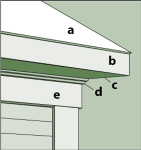
The eave of a roof system is the outer edge of a roof that encompasses the entire perimeter of the roof.  Most eaves are the “closed” type with a soffit section between the outer edge of the roof perimeter and the building wall.

Below is a breakdown illustration of a typical eave section:

A. Roof – The upper exterior surface of the home.

B. Fascia – A flat horizontal band around a roof’s perimeter.

C. Soffit (Or Box Eave) –An overhang enclosed with a ventilated soffit section that runs horizontally from the eave edge to the side of the building.

D. Cornice –The decorative section just below the roofline. The cornice may be simple or ornate depending on building style.

E. Rake –The pitched edge of a gable roof. Rakes may be close, or extend from the building to allow for an overhang.

The complexity or simplicity of a roof design is normally a combination of engineering specifications and aesthetic preferences, but most roofs fall within the categories described above. Resistance to wind forces during extreme weather conditions is also a function of a roof’s design and shape. This is particularly important to insurance professionals to determination to determine your homeowner’s insurance policy. As A SkyTech client feel free to ask us questions ab0ut your roof and any details that we have provided in your inspection report.

Saving On Energy Costs This Winter

Saving On Energy Costs This Winter

Saving On Energy Costs This Winter

Winter is fast approaching. If you’ve questioned whether your house is insulated enough to provide you with warmth at home and save money on your heating bills, now is the time to understand the R-Value of your home and to deploy some strategies that will help with heating your home and lowering your heating costs. The energy saving tips in this article and an understanding of R-Value and insulation (explained below) will get you started for the sake of your personal comfort, and to ward off a scary heating bill.

10 Ways to Save on Energy Costs This Winter

  1. Use the sun for free heat. …
  2. Bundle up with warm accessories. …
  3. Use ceiling fans to your advantage. …
  4. Adjust the thermostat at night. …
  5. Only heat the rooms you use. …
  6. Keep your furnace clean and unblocked. …
  7. Get a humidifier to add moisture to the air. …
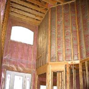
  8. Invest in insulation.
  9. Decorate with LED lights for the holidays.
  10. Only use exhaust fans when necessary.

Click this link from US News for more information on these suggestions.

Insulation R-Value Defined

Energy efficiency has become an increasing concern to homeowners and the Real Estate and Property Insurance Industries. The performance of the insulation products installed in a building or dwelling are important factors to be considered when building, purchasing, or renovating a home or commercial property.

R-Value Defined

RValue is defined as “The measurement used when quantifying the level of a specific material’s thermal resistance”.

How Does R-Value Relate to Insulation?

The function of insulation is to provide resistance to the flow of heat, and R-Value is the measure a material’s resistance to this heat flow.

A high R-value equates to higher resistance to heat flow. An insulation material’s R- Value, in conjunction with where and how it is installed, determines its overall effectiveness.

Quick Fact

Heating and cooling costs for a typical home in the US account for approximately 65% of the home’s total monthly energy usage.

Factors to Consider Regarding Thermal Resistance

When considering R-value as a means to determine the thermal resistance of a building component, there are other factors that must also be taken into account. While R-values are an excellent guide for comparing the attributes of different insulation products, they apply only when the insulation is properly installed.

• For example, if two layers of insulation are compacted and forced into the space intended for only one layer, the R-value does not double.

• Likewise, if a single layer of insulation is compressed during installation, it will not be as effective. Stuffing “batt”-type insulation sized for 5 inches into a 4-inch wall cavity will actually lower its R-value!

• Ensuring that insulation is correctly installed will help allow the product’s full benefits to be realized.

Calculating and Converting R-Value

The equation used to calculate R-value can be helpful not only to Industry Professionals, but it can be helpful to Homeowners as well.

If the R-Value of the insulation is known, the following equation can be used to help calculate heat loss. The equation for determining R-value is as follows: R-Value = Temperature Difference x Area x Time

Heat Loss

  • The Temperature Difference is expressed as T (“Delta T”) and is measured in degrees Fahrenheit (Deg F)
  • The Area is expressed as A and is measured in Square Feet (Sq Ft)
  • The Time is expressed as T and is measured in Hours (H) The Heat Loss is expressed as L and is measured in British Thermal Units (BTU)
  • R-Value = T x A x T / L

Current Regulations Regarding R-Value

In the 1970s, the Federal Trade Commission (FTC) created a rule requiring insulation manufacturers to disclose the R-Value of insulation material. This was intended to protect purchasers from false manufacturer claims, as well as to create a standard by which insulation products could be compared. The U.S. Department of Energy (DOE) regularly issues recommendations for insulation R-values in new and existing homes. The recommendations are based on a comparison of the cost for installing insulation versus potential future energy savings.

Quick Fact

The DOE R-Value recommendations for attics, cathedral ceilings, walls and floors are generally greater than what is actually required by most current building codes.

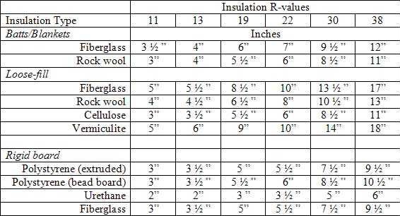
R-Value Thickness Comparison Matrix

Below is a simple matrix that can useful in determining the R-Value of a material as compared to its thickness:

Knowledge of R-value ratings can be useful, especially when comparing the effectiveness of insulation products, but understanding a bit about how other factors affect a building component’s thermal resistance is important if insulation is to be used to its full benefit. Industry Professionals who are familiar with the basics of insulation R- values can provide “value-added” to their clients should questions regarding a property’s energy efficiency arise.

Water Heater Basics

Water Heater Basics

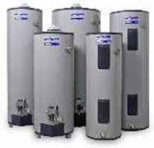
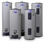
Most residential dwellings have a tank-type water heater which consists of a cylindrical free-standing tank with plumbing supply and outlet lines at the top of the unit. The most common heat sources for tank water heaters are electricity or gas (either propane or natural gas).

An electric water heater will have a large electrical conduit attached from the dwelling’s main electrical power source (main circuit breaker panel).

A fuel-type or “gas fired” unit will have a large vent duct at the top and a fuel source line close to the bottom of the unit.

A tank water heater not only heats water but stores it until it is needed. This is why all tank water heaters are fitted with insulation material that helps maintain the water at a high temperature between heating cycles.

Tank Water Heater Operation

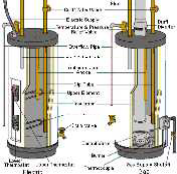
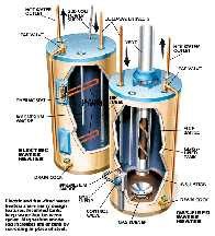
At the top of all tank water heaters there are the water supply and delivery lines. The supply pipe routes cold water to the bottom of the tank through a Dip Tube. A Delivery Pipe takes water from the top of the unit and delivers it to whatever plumbing fixtures need it such as clothes washers and faucets.

All tank water heaters are equipped with a safety device known as a T&P Valve (temperature-and-pressure relief valve). This valve is designed to open if either the temperature of the water or the pressure inside the tank exceeds a safe limit.

Quick Fact

The T&P valve of a tank water heater is required to be plumbed to expel high-pressure, hot water the exterior of the building or dwelling if the water heater unit is installed on the same floor level as the living area of the home, or if it is installed in the attic space.

If the tank unit is installed below the main floor level of a home (as in the lower floor
area of a garage, it may be plumbed to expel to a drain pan installed below the tank unit.

Tank Water Heater Construction

Most tanks are made of steel with an interior glass lining to help prevent internal corrosion. All tanks also have an Anode Rod designed to control corrosion.

The anode rod essentially protects the tank by corroding in place of the steel. Because the rod is designed to corrode, it will eventually wear out and need to be replaced. It’s a good idea to check the anode rod once a year, and replace it if necessary.

At the bottom of every tank is a drain for emptying the tank. There is also valve on the supply pipe (usually at the top of the unit) which allows the ability to shut down the hot- water plumbing without affecting the cold-water supply to the home.

Electric Water Heaters

A typical electric unit is wired to a 220-volt circuit. To heat the water, current passes through heating elements—usually two, one at the middle of the tank and one at the bottom, via a thermostat (a switch that senses water temperature). When the temperature of the water drops below a preset value, the switch closes to allow current flow and opens again when the temperature reaches its preset limit. Most thermostats have a dial for setting the maximum water temperature.

Fuel-Fired Water Heaters

Gas water heaters have an internal burner that is fed fuel through a control valve and a thermostat switch. This burner is usually situated so that the tank is heated by the flame from the burner. Exhaust gases are vented either through a hollow core at the center of the tank or around the tank sides.

Quick Fact

Because fuel-type water heaters use actual flames to heat the water in the tank, the unit experiences a higher degree of material wear and degradation when operating. The life expectancy of a gas-type water heater is usually less than an electric unit.

Heater Effectiveness

The capacity of the tank, and the rate at which water is heated, affect the supply of hot water at the plumbing fixtures.

The speed at which a unit heats water is called its recovery rate. This figure indicates the amount of
water in gallons that can be heated to 100 degrees F in 1 hour. When water is drawn from the tank faster than it is being heated (as during a 45 minute College Student shower…), the temperature of the water will drop. This is commonly known as “Running out of hot water”.

Typically, heaters with low recovery rates have a high tank capacity. Although it takes longer to heat the water, there’s more of it for intermittent use. Electric units fall into this category. Conversely, a fuel-fired heater with a high recovery rate needn’t have as large of a large tank, because it can heat the water faster. In general, electric models have the lowest recovery rate, and gas units have the highest.

Tankless Heaters

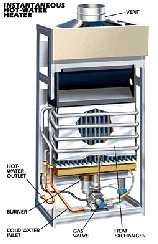
Tankless water heaters are becoming more and more common due to their energy efficiency and virtually unlimited supply of hot water. They are available in both electric and fuel-fired (gas) varieties. Because tankless heaters only heat water as it’s used, no energy is required to maintain water at a specific temperature for long periods of time like the tank-type units.

Tankless Unit Principle of Operation

The tankless system uses a heat exchanger to heat the water. The heat exchanger aids in transferring the heat from the gas burner (gas heater) or electric coils (electric heater) to the incoming cold water.

When a hot water tap is opened, incoming cold water passes through the heat exchanger. The heat exchanger heats water according to the specified temperature and hot water is supplied back to the tap via the hot water piping system.

There is flow sensor or flow switch which detects the water flow and turns on the system to heat the water.

Regardless of the type of unit installed, a basic understanding of the principles of water heater operation is helpful when advising clients during the real estate or insurance transaction process.

Ground-Fault Circuit Interrupters (GFCIs)

Ground-Fault Circuit Interrupters (GFCIs)

Ground-Fault Circuit Interrupters (GFCIs)

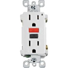
A ground-fault circuit interrupter, or GFCI, is a device used in residential and commercial
buildings that is designed to disconnect a circuit when unbalanced current is detected between an energized wire and a neutral return wire. Such an imbalance is sometimes caused by current “leaking” through a person who is simultaneously in contact with a grounded conductor and an
energized part of a circuit. This condition has the potential to create a lethal shock.

Standard circuit breakers are designed to protect against voltage and current overloads as well as short circuits, but will not trip during a ground fault condition.

QUICK FACT

It is estimated that about 300 deaths by electrocution occur every year. The use of GFCIs has been adopted as a requirement in virtually all new construction, and recommended as an upgrade in older construction in order to mitigate the possibility of injury or fatality from electric shock.

HISTORY OF THE GFCI

The first high-sensitivity system for detecting ground faults was developed by Henri Rubin in 1955 for use in South African mines (no kidding!). His design caused a ground-faulted circuit to de- energize or “trip” before electric shock could drive a person’s heart into ventricular fibrillation, which is usually the specific cause of death attributed to electric shock.

The first transistorized version of the GFCI was developed by Charles Dalziel in 1961. Through the 1970s, most GFCIs were of the circuit-breaker type. This type of GFCI was prone to frequent false trips, especially in circuits with long cable runs. Since the early 1980s, GFCI’S have been built-in to outlet receptacles, and advances in design have improved reliability while reducing instances of “false trips,” also known as “nuisance-tripping”.
A PRACTICAL EXAMPLE OF A GROUND FAULT IN THE HOME

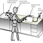
Suppose a bare wire inside an appliance (clothes iron, hair dryer, popcorn maker, toaster, etc.)
touches the metal case of the appliance.

The metal case just became charged with electricity!

If you were to touch that appliance with one hand while the other hand is touching a grounded metal object, like a water faucet, you will receive a shock because you just became a conductor for current.

If the appliance is plugged into a GFCI outlet, power will be shut off before a fatal shock would occur.

The GFCI interrupts the current flow before it can hurt you!
BASIC OPERATION OF THE GFCI

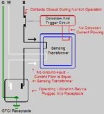
The operation of a GFCI is really quite simple. It compares the amount of current going out to the load (lamp, hair dryer, microwave oven, etc.) and the amount of current returning from that load.

It uses a Current Transformer Circuit (CT) to compare the difference between these current amounts.

If the current going out to the load equals the current coming back, there is no “leakage to ground” (Ground Fault), the output from the Current Transformer Circuit is zero, and everything’s fine.

If there is an imbalance in current (ground fault), the CT circuit will determine if the fault is sufficient to necessitate the interruption of the current flow (Hence the name Ground Fault Circuit Interrupter). SIMPLE!
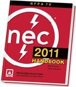
GFCI’S AND THE NATIONAL ELECTRICAL CODE (NEC)

The National Electrical Code (NEC) has included recommendations and requirements for GFCIs in some form since 1968, when it first allowed for GFCIs as a method of protection for underwater
swimming pool lights.

Throughout the 1970s, GFCI installation recommendations were gradually added for 120-volt receptacles in areas prone to possible water contact, including bathrooms, garages, and any receptacles located outdoors.

The 2011 NEC is the most up to date code source and contains additional updates relevant to GFCI use, as well as some exceptions for certain areas.

As always, your AccuTech Professional will be able to answer any specific questions that arise with regards to NEC requirements and recommendations.

TESTING OF RECEPTACLE-TYPE GFCI’S

Receptacle-type GFCIs are currently designed to allow for safe and easy testing by a property owner without the need for any professional or technical knowledge of electricity.

GFCIs should be tested once a month to make sure they are working properly and are still providing protection. The first method below does not required specialized “tester” to perform. The second method requires the use of a UL approved GFCI circuit tester that can be purchased for about $10-$15 and any hardware store.

IMPORTANT SAFETY NOTE: IF YOU DON’T FEEL COMFORATBLE TESTING YOUR GFCI OUTLETS, CALL A PROFESSIONAL!!!

To test a receptacle GFCI without a specialized GFCI Tester:

• Ensure that the outlet is functioning by plugging in a nightlight or other small appliance into the outlet (with the appliance OFF). Turn the appliance ON. The appliance should operate normally.
• Press the “TEST” button on the GFCI outlet. The “RESET” button should pop out with an audible click, and the light / appliance should turn off.
• If the “RESET” button pops out but the appliance does not turn off, the GFCI has been improperly wired. Contact a licensed, certified electrical specialist to correct the wiring error(s).
• If the “RESET” button does not pop out, and the appliance remains powered, the GFCI is defective and should be replaced.
• If the GFCI is functioning properly and the appliance turns off, turn off and disconnect the appliance, press the “RESET” button to restore power to the outlet, and re-connect the
appliance is desired.

To test a receptacle GFCI using a UL Approved GFCI Tester:
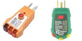
• All UL approved testers come with brief instructions. Read the instructions first!
• Insert the GFCI test plug into the powered outlet. All UL-Approved testers have a small “Indicator Light Matrix” that describes each light condition when testing (see photos at right).
• The lights corresponding to a NORMAL condition should be illuminated if the outlet is powered and wired correctly.
• If any other light configuration other than NORMAL is illuminated, the outlet is incorrectly wired and an electrical specialist should be contacted to correct the defect.
• Press the TEST button on the tester. All lights on the tester should go out and the
RESET button on the outlet should pop out, indicating that a simulated ground fault condition has occurred. If this does not occur, the outlet is defective and should be replaced.

GFCI outlets are simple and cost-effective safety devices that help to prevent electrical shock hazards in a home or building. As Industry Professionals, a basic understanding of their purpose and operation is helpful.